Skip to content
SONNWINN
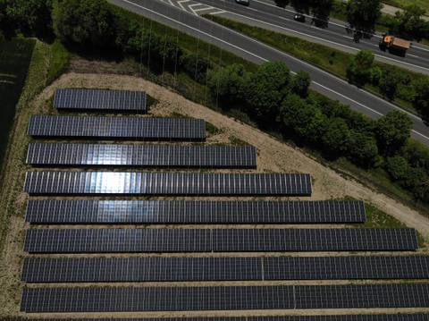
Aerial view of a ground-mounted photovoltaic system next to a motorway: the reflection of the sun is visible as a bright spot on some module rows

Glare assessment for PV systems in Germany

Reflections from PV systems at residential buildings, on roads, railways and in air traffic – calculated and assessed according to the relevant regulations.

Background

Photovoltaic modules reflect part of the sunlight. Depending on the position of the sun, the module orientation and the surroundings, these reflections reach residential buildings, roads, railway lines or flight paths and can cause glare there.

Under the BImSchG (German Federal Immission Control Act), light immissions are harmful environmental effects if, by their nature, extent or duration, they are liable to cause hazards, for example to road traffic, or significant nuisance to the neighbourhood. PV systems that do not require a permit under this act must also be built and operated so that avoidable harmful light immissions are prevented and unavoidable ones are reduced to a minimum.

A glare assessment is therefore often required in land-use planning or in the permitting procedure. It is advisable already at the design stage: necessary measures can then be included with little effort, whereas modifying existing systems afterwards is usually expensive.

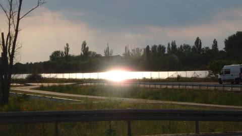
Low sun behind a ground-mounted photovoltaic system: the module rows behind the fence reflect the low sun, with a road and crash barrier in the foreground
Basis of assessment
AffectedBasisCriterion
Residents (protected rooms)LAI (German Working Group on Immission Control) guidance on light immissionsat most 30 min per day and 30 h per year of core glare
Road and rail trafficKey points paper of the FBA (Federal Highway Authority, Fernstraßen-Bundesamt)reflections in the field of view ± 30°, luminance 30,000 cd/m²
Air traffic§ 12(3) LuftVG (German Aviation Act), evaluation according to CIE 146glare to pilots and air traffic controllers in the field of view

There are no statutory limits for light immissions. The LAI guidance has become established as the standard in permitting practice.

Service levels

Whether a preliminary analysis is useful before the assessment depends on the design stage.

Starting point

Design stage and requirements

Location of the PV areas, stage of the design and requirements of the authority or public agencies, for example regarding specific residential buildings, traffic routes or an airfield.

Decisive: whether the design is fixed or several variants are still possible.

If: several design variants are possible, e.g. layout, orientation, tilt or tracking

Level 1

Preliminary analysis

Comparison of the glare effect of the variants at the same residential buildings and traffic routes, with an approximate indication of possible measures for each variant.

Result: written initial assessment with a recommendation on which variant to pursue.

Level 2

Glare assessment for the chosen variant

Assessment for the permitting procedure; where glare is found, with measures and proof of their effect

If: the design is fixed

Level 2

Glare assessment

Calculation and assessment for the planned system at all relevant residential buildings and traffic routes, including air traffic where required.

Assessment for the permitting procedure; where glare is found, with measures and proof of their effect

Areas of investigation

Which areas an assessment covers depends on the location of the system and the requirements of the authority. Each area is assessed according to its own regulations.

Residents

Observation points at the windows of protected rooms (e.g. living rooms, offices). Core glare is assessed under the LAI guidance: at most 30 minutes per day and 30 hours per year. Reflections that appear no more than 10° from the sun are masked by it and are not counted. Results for each observation point with periods (month and time of day) and glare duration per day.

Road and rail

Observation points along the traffic routes, with a separate field of view for each direction of travel; eye height 2.7 m (lorry), on railway lines 2.5 m (train driver). Assessed according to the FBA key points paper: reflections in the field of view of ± 30° are only disregarded if the sun masks them, their luminance is below 30,000 cd/m² or the glare source is very small outside ± 10°. The results are classified according to the importance of the traffic route.

Air traffic

Observation points on the approach path (glide path up to the threshold), at the tower and on taxiways. Positions and heights from the Aeronautical Information Publication (AIP). Evaluation according to CIE 146 via the increase in the perception threshold caused by the glare, taking into account luminance, illuminance at the eye, size of the glare source and position in the field of view.

Rooftop systems

Rooftop systems on residential and commercial buildings, before installation or for existing systems, for example in the case of complaints from the neighbourhood. The assessment follows the same regulations; for buildings near airports, it includes air traffic.

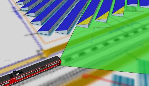
3D model of a PV system next to a railway line: field of view of the train driver in green, reflection zones on the module rows marked in yellow
Railway: train driver's field of view and reflection zones in the 3D model
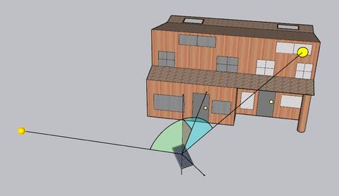
3D model of a residential building: reflection lines lead from a module to an upper-floor window, sun position and angle of incidence are drawn in
Residents: reflection from a module to the window of a house in the 3D model

Calculation

We simulate the reflections for a full year in one-minute steps, with the position of the sun at the site, the planned system and the terrain. The calculation is carried out with the simulation software PV-GlareCheck.

For each observation point the simulation shows from which direction, at what times and for how long reflections occur and whether they lie in the field of view.

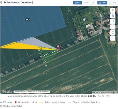
Reflection map from PV-GlareCheck: reflection directions from a PV area to an observation point on a road, with the driver's field of view
Reflection map in PV-GlareCheck. Aerial image: © GeoBasis-DE/LGB (2026), dl-de/by-2-0

Contents of the assessment

  1. Summary with the result for each residential building and traffic route
  2. Description of the system and its surroundings: location, terrain, system parameters, obstacles taken into account
  3. Input data: all inputs with document, source and date
  4. Assessment criteria and simulation method
  5. Results for residents: tables and charts for each observation point, core glare and realistic values shown separately
  6. Results for traffic routes: reflections in the field of view, classified by the importance of the route
  7. Measures with calculated proof of their effect, where required
  8. Appendix: assumptions and limits of the simulation, maps, data sheets
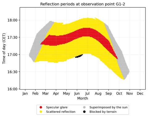
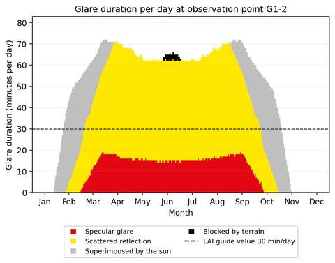
Chart of reflection periods at an observation point over the year: specular glare red, scattered reflection yellow, superimposed by the sun grey, blocked by terrain black Chart of glare duration per day at the same observation point, with the guide value of 30 minutes per day as a dashed line
Excerpt from an assessment: when reflections occur at a residential building and how long they last each day

1,300+ glare assessments and expert statements by our experts since 2021 – for ground-mounted and rooftop systems, next to motorways, railway lines and airports, in Germany and abroad. References

Measures against glare

If guide or limit values are exceeded, we set out solutions and demonstrate their effect with a new simulation. The aim is an economical solution that can be secured as a condition in the permit.

The earlier glare is taken into account in the course of the project, the greater the scope for a solution.

Possible measures

  • Adjusting the geometry: azimuth and tilt of the modules, rotation of individual tables, east-west mounting
  • Visual screen: opaque fence or dense planting, height and length determined from the lines of sight
  • Low-glare module surfaces, recalculated with the reflection profile stated by the manufacturer
  • For tracking systems: rest angle and stow and storm position
  • Comparison of variants under the same assumptions

Process

  1. Enquiry: location of the system and, if available, the requirement of the authority
  2. Quote with scope, costs and schedule
  3. Documents: we check them for completeness and request missing information specifically
  4. Simulation and evaluation, where limits are exceeded with measures and proof of their effect
  5. Assessment as PDF, usually two to three weeks after complete documents are available
  6. Statements on queries from the authority or public agencies

Further services

Tracking systems

Geometric proof for single-axis tracking systems (trackers), including stow and storm position.

Expert statements

Technical statements on queries from the approval authority and public agencies.

Existing systems

Assessments in the case of complaints, including court expert reports answering the questions put by the court.

Assessments in English

Glare assessments in English, including for air traffic.

RPS analysis

For systems next to motorways and federal roads, the check of distances according to RPS.

Glare and noise assessments

For PV projects with storage, also the noise assessment.

Frequently asked questions

What is a glare assessment?

A glare assessment determines and evaluates the reflections of a planned or existing photovoltaic system at the surrounding buildings and on traffic routes, and where required for air traffic. It shows when and for how long reflections occur, whether the relevant guide or limit values are met and which measures can prevent glare.

Is a glare assessment mandatory for a PV system?

There is no general statutory obligation. However, a glare assessment is often required in land-use planning or in the permitting procedure by the authority or by public agencies, for example the road administration, the railway or the aviation authority. Irrespective of this, under the German Federal Immission Control Act, PV systems must be built and operated so that harmful environmental effects caused by light are avoided or reduced to a minimum. The assessment provides the evidence for this.

How much does a glare assessment for a photovoltaic system cost?

Costs depend on the scope and complexity of the project, for example on size and number of PV areas, number of residential buildings and traffic routes to be examined, whether air traffic has to be considered and whether variants or measures have to be demonstrated. After a short description of the project, you receive a quote in advance.

How long does a glare assessment take?

Usually two to three weeks after receipt of complete documents. If it is urgent, please contact us.

What is a preliminary analysis in a glare assessment?

The preliminary analysis compares the glare effect of several design variants, for example east-west versus south orientation or different module tilts, at the same residential buildings and traffic routes. For each variant it shows where guide or limit values are likely to be met and which measures, such as a visual screen, would be needed. The result is a written initial assessment with a recommendation on which variant to pursue; the glare assessment for the permitting procedure follows for the chosen variant.

When is a preliminary analysis worthwhile?

When several design variants are still possible, for example in layout, orientation, tilt or tracking. The preliminary analysis then shows early on which variant causes the least glare and which measures would be needed for the others. If the design is already fixed, the glare assessment is prepared directly.

Which limits apply to neighbouring residential buildings?

According to the guidance of the German Working Group on Immission Control (LAI) on the measurement, assessment and reduction of light immissions, glare at a protected room, such as a living room or office, is considered a significant nuisance if it occurs for more than 30 minutes per day or more than 30 hours per calendar year. The assessment is based on core glare, i.e. the reflection from an ideally specular module surface.

How is glare on roads and railway lines assessed?

The basis is the key points paper of the Federal Highway Authority (Fernstraßen-Bundesamt, FBA). Reflections in the relevant field of view of the drivers (± 30° to the direction of travel) are considered. They are not counted if they are masked by the low sun, if their luminance is below 30,000 cd/m² or if the glare source is very small outside the central field of view (± 10°). Remaining reflections are reported in the assessment with their duration and the PV area concerned. Unlike for residents, the key points paper does not set a time limit.

Do I need a glare assessment near an airport or airfield?

If a planned PV system is located near an airport or airfield or in its approach path, the consent of the competent aviation authority under Section 12(3) of the German Aviation Act (LuftVG) may be required for its construction. The authority also examines whether glare could affect air traffic. A glare assessment that considers the approach, the tower and taxiing traffic provides the basis for this.

What does a glare assessment for air traffic examine?

It examines reflections on the approach path up to the runway threshold, at the tower and, depending on the location, on taxiways and runways. We take the position of the approach paths, thresholds and glide angles from the Aeronautical Information Publication (AIP). The evaluation takes into account luminance, illuminance at the eye, size of the glare source and its position in the field of view of pilots or air traffic controllers.

What is the difference between core glare and realistic reflection?

For core glare, the module surface is calculated as an ideal mirror. This model is the basis of the assessment under the LAI guidance. Real modules also scatter the light; the realistic simulation with the reflection characteristic of the module shows the larger area in which scattered reflections are visible. Both results are reported separately in the assessment.

Is there a certified glare assessment?

There is no certification for glare assessments. What matters is that the assessment follows the recognised guidelines – the LAI guidance for residents, the FBA key points paper for roads and railways and the requirements of the aviation authority –, that all input data are documented with their source and that the method is described in a traceable way. This allows the authority to check the result.

Does an anti-reflective coating prevent glare?

No. Practically all modules today have an anti-reflective coating. It mainly serves to increase yield and reduces reflection by a few per cent, but on its own it does not rule out glare. The assessment therefore uses the reflection characteristic of the module actually planned.

Does this also apply to agri-PV, floating PV and tracking systems?

Yes. The same guidelines apply; the geometry of the system is modelled exactly in the simulation, for example elevated or vertical modules in agri-PV. For tracking systems the module position is calculated for every point in time, including stow and storm position.

Which documents are needed for a glare assessment?

At least the location of the PV areas and the orientation of the modules (azimuth and tilt). For a reliable calculation, module heights (lower and upper edge), table design, module type with data sheet and, for tracking systems, the rotation range, stow and storm position are also needed. For rooftop systems, a roof plan and building elevations are added.

Are glare assessments also available for rooftop systems on houses?

Yes. Smaller rooftop systems usually do not require a permit, so glare often only becomes apparent after installation. A glare assessment can show before installation whether the neighbourhood is affected, or determine the extent of glare for an existing system, for example in the case of complaints.

What happens if the assessment finds glare?

We then set out measures that avoid the glare and demonstrate their effect by calculation – for example a changed module orientation, a visual screen of a certain height and length or low-glare module surfaces. The earlier this is done in the design, the greater the scope.

Enquiry

Use the form, call us on +49 4103 121 4221 or write to kontakt@sonnwinn.de – whichever suits you best.

You do not need to attach documents to your enquiry – once we have received it, we will help you put together the documents required.

Which documents are helpful
  • Location of the PV areas (site plan, KML or shapefile)
  • Module orientation: azimuth and tilt; for tracking systems rotation range, stow and storm position
  • Module heights (lower and upper edge), table design and row spacing
  • Module type with data sheet
  • For rooftop systems: roof plan and building elevations
  • If available: requirements or comments from the authority, for example regarding specific traffic routes or an airfield
Service

Technical inspections

Assessments

Planning and consulting

Other

Project
Contact
* Required